Modifying The Analog Board
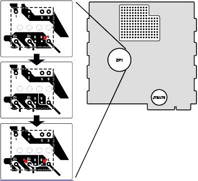
In the first pane of this diagram, a red arrow points to the 8-pin (power supply transformer).
In the second pane of this diagram, the 8-pin has been correctly isolated using the dremel.
In the third pane of this diagram, a soldering iron is used to connect a piece of wire from the 10-pin to the 8-pin.
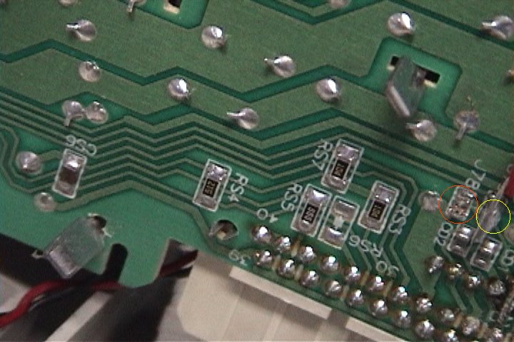
The other circle in the diagram is the location of J78 and J79.
Remove J78 using the soldering iron.
Create a solder bridge across J79 (you can do this by applying solder to J79 like a "bridge").
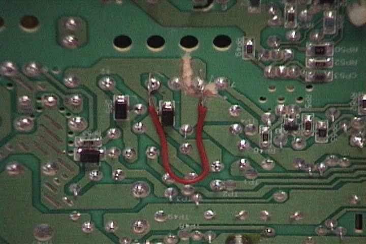
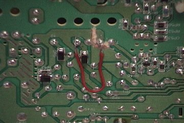
As you can see in the image below, the 8-pin is isolated and a wire is connecting the 10-pin to the 8-pin.
Ignore the wire for the moment and use the dremel to isolate the 8-pin. Be sure it is isolated by using a meter to test the connection!
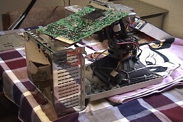
When you're ready to solder the wire, place the chassis next to the bottom end of the front panel and lift the analogue board up onto the chassis. [NOTE: I do NOT recommend placing ANY pressure on the CRT whatsoever as the neck is very fragile and if broken, will destroy the CRT. -cl]
Now cut a small (2 inches or so) piece of wire and solder it from the 10-pin to the 8-pin.
This is where J78 and J79 are located. J78 is inside the red circle and J79 is inside the yellow circle.
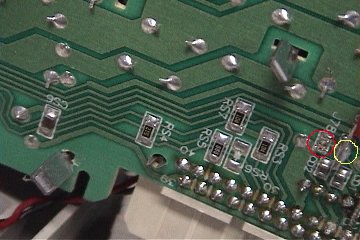
Missing J78 and J79 on your analogue board? Click here for a solution.
Now you can reassemble the computer but leave the case off!
Make sure you test ALL connections you made/modified before you reassemble it!
Previous Page | Next Page