iMaCC Upgrade
Brad R. Sturges has completed the CC-to-iMac upgrade and has kindly agreed to share step-by-step instructions for performing this upgrade. Please direct specific questions about the upgrade to Chris Lawson. They will be forwarded to Brad, allowing this document to be kept up-to-date, accurate, and as detailed as possible.
Parts and Equipment List
- Color Classic
 Logic board and processor from any tray-loading iMac
- 1U rack-mount ATX power supply capable of delivering at least 180 watts
- 2" processor fan (for cooling the iMac's CPU)
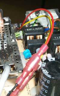
- Several crimp-on male and female connectors (10 pairs should be sufficient; see photos at right and below)
- 2.5" IDE hard drive
- 2.5"-to-3.5" IDE adapter board
- IDE ribbon cable, at least 9" long
- Dremel or other rotary tool
- Quality soldering iron
Notes on parts and equipment:
- Obviously, in order to complete the project, you must have a CC with a working analogue board, CRT, and floppy drive. However, these are the only original parts that must be working. If you don't care about the floppy drive, you only need a working CC analogue board and monitor. If you need a CC for this modification, try checking eBay.
- The logic board and processor are the only parts of the iMac you cannot do without. However, other parts are helpful if you can get them. The three connectors that attach to the logic board (video, audio, and power filter connectors) make the project easier. The iMac's speakers are a nice addition and will give you stereo sound.
- Most dead iMacs have died because of a failed power supply and/or video board. The logic board and all other parts are usually fine. Dead iMacs are cheap on eBay but shipping can be costly, so plan accordingly. If you can get the seller to dispose of the CRT and case, shipping will be much cheaper. While getting all the optional parts from a complete iMac is best, the project can be done with only the logic board and processor.
- Since the CC's analouge board is not powerful enough to drive an iMac logic board, an additional power supply is needed. This power supply's size is good for the project as it fits nicely in the hard drive bay. It will power everything except the CC display. I have found that an Achme PSU for a flex-ATX case works even better than the rack-mount PSUs. Although the metal casing of the Achme PSU must be removed, this PSU is smaller and produces less heat.
- Since the new power supply takes up the hard drive bay, a smaller hard drive is needed to be fit in a tighter spot. A 9.5mm drive works best, but taller drives may work. An adapter to allow the drive to be plugged into a standard IDE cable is required. Adapters can be found at most computer parts suppliers. The IDE cable that comes with the iMac is too short so a slightly longer one is needed. Depending on where you end up placing the hard disk, this could be as short as nine inches or as long as a couple feet. Plan ahead.
- While a rotary tool is not absolutely essential, it will be difficult to perform the necessary chassis modifications and the VGA modification without one.
Performing the Upgrade
Tampering with a CRT can be dangerous. You should only perform this modification if you are comfortable with electronics and understand the safety precautions that should be taken when dealing with a CRT.
- Perform the VGA upgrade on the CC. You only need to perform the first two steps of the VGA upgrade.. The iMac ignores the sense lines entirely and assumes the monitor hooked up to it is VGA.
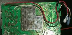
 Now, solder on the three wires that will power your new PSU. Locate the three pins on the underside of the analogue board that are supplied with AC power when the switch is on. Be sure to use wire capable of handling the current; 14-gauge wire should suffice. Crimp a quick connector on the end of each wire for easy disassembly in the future.
 The final analogue board modification is to supply power to the fan connectors located near the power switch. The original wiring will not power the fan unless the analogue board "knows" the computer is on. This modification neuters the analogue board's ability to "know" whether or not the computer is running. Isolate these connectors using the same technique as you used for the VGA modification. Once isolated, solder two wires to them with connectors crimped on the ends. You'll eventually use these to attach 12v lines from the new power supply.
- You must now clear out the chassis to make room for all of the new components. First, remove the slots on the chassis that the hard drive sled slides into. The power supply will only fit under the analogue board if these tracks are gone, as it must lay flat on the very bottom of the chassis "shelf." This can be done easily with a rotary tool.
 The underside of the chassis (where the original motherboard resided) must be cleared out as well. Remove the material in this area to make sure you have as much room as possible. Again, a rotary tool makes this very easy, though a good portion of this can be achieved with a small hacksaw too.
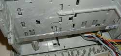
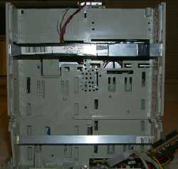
 Now you need to develop a support structure for the iMac motherboard. Cut slots in the side of the chassis and place supports in these slots. (You can see one of them in the photo above, and again in the photo at right.) Metal strips are cheap and easy to find, but be sure to insulate them with plenty of electrical tape. Wood or plastic can be used too — you just need something that can support the weight of the motherboard. One piece should an L-shaped bracket, which is used to create a stop in the front of the chassis so the motherboard could not be pushed too far into the chassis. Make sure you place this piece such that the ports are flush with back of the CC when the board is fully inserted.
- Now we can move on to connecting up the power supply. With a wire cutter, remove the 20-pin connector of the power supply as close to the connector as possible. You want these wires to be able to reach down to the motherboard from the HD bay, since they will be used to power the motherboard. Most 1U power supplies fit without modification, but the Achme flex-ATX power supply requires that the outer metal casing be removed first. If you choose this PSU option, you must make sure the holes that mount the PSU circuit board to the casing are properly grounded.
- In the iMac, the motherboard plugs into a power filter that sits directly below the motherboard. While this unit is not needed, its connector greatly simplifies the connection of wires to the bottom of the motherboard. Otherwise, you must solder directly onto the motherboard and will have no way of easily connecting and disconecting the power. To use the connector, simply cut off the power filter connector with a rotary tool, place it on a small piece of blank PCB, and solder the wires onto the back of the connector.
- Now you're ready to wire up the motherboard itself. You'll need to consult the iMac Rev A-D Pinouts for the correct pinouts. (The pin numbering assumes the orientation of the board is with the processor cage facing the ground, and all the ports facing right.) The number of wires needed does not precisely match up to the number of wires you have on the power supply, but it won't matter as long as you double up where necessary. For example, if the motherboard needs a red wire on a pair of pins on the same vertical row, simply solder one wire to both of them. The only issue is that the iMac motherboard requires two +12V (yellow) wires and the PSU only has one in its main connector. Just use a yellow wire from one of the spare hard drive connectors instead.
- Once you've made the connections to the motherboard, you can now make the rest of the connections you need. You will need to plug a hard drive power connector into your 2.5" IDE hard drive's adapter board. Where you mount the hard disk is really up to you, as its small size allows a nearly limitless array of mounting options. Secure it to a rigid surface if you plan to transport the computer anywhere.
- Crimp a quick-connect terminal onto one yellow wire from the PSU and do the same for a black wire. Then, connect these two wires to the power wires you soldered on for the fan contacts. While you're at it, connect the wires from the analogue board's power input to the new PSU. Be sure to match the hot, neutral, and ground wires properly.
- Now you can move on on to the video connections. Remember, you should have performed the first two steps of the VGA hack already. The connections to be made between the CC's analogue board connector and the iMac's video connector are as follows, with all pin numbers referring to either the Takky Connector Correlation Tables (CC analogue board) or iMac Rev A-D Pinouts (iMac board). Colours have been matched to the iMac Rev A-D Pinouts for consistency.
iMac Video Connector Pin (function) | CC Analogue Board Pin |
|---|
1 (R ground) | 14 |
2 (R signal) | 15 |
3 (B ground) | 10 |
4 (B signal) | 11 |
5 (G ground) | 12 |
6 (G signal) | 13 |
8 (horizontal sync) | 9 |
10 (vertical sync) |
9 (sync ground) | 8 |
11 (contrast control) | 19 |
15 (contrast control ground) | 18 |
Notes on performing the upgrade:
- Note about mobo wiring: The first four pins (pins 1-4 on the diagram of the PSU connector) on the motherboard simply go to the hard drive power source connector on the motherboard. You can choose to use the motherboard's power connector or not; if you aren't going to use it (and instead are planning to use one of the connectors built into the PSU), you can leave this pins disconnected.
- Note about soft-power: In order to allow the iMac to start up—or "soft-power"—an ATX power supply, a small circuit is needed. People have had varying degrees of difficulty getting this circuit working. If you wish to avoid it entirely, you can ground the green wire on the PSU. If you do this, the switch in the back of the CC powers up the computer, and when you select shut down, the OS shuts down and you simply flick the switch to turn off the computer's power, just as with the LC "pizza-box" Macs.
- Note on the
contrast control ground connection: the display will work without this connection. However, if you set your display to sleep via the Energy Saver control panel, this connection causes weird behavior during display sleep. About half of the times the display goes to sleep, it will display a weird gray wavy image. The rest of the times, it turns off as expected. Without this connection, display sleep is always what it should be, but it takes longer to awake from sleep than if the connection is made. Your call.
- Note: the floppy drive works fine under OS 8.6 even with the latest firmware (required for post-8.6 Mac OS versions). However, the floppy drive does not work under Mac OS 9.2 or OS X. At this point, it's unclear if the floppy drive will work if you revert to 8.6 after having a newer OS installed, so if floppy support is vital to you, stick with Mac OS 8.6 and watch this space for updates.
- One final video note: Mac OS X (all versions) will automatically reset the connected monitor to 800x600 (SVGA) during installation and start-up. This obviously creates problems for this hack. To get around this, connect an external monitor to the appropriate pins on the motherboard during installation. You can then use SwitchRes ($15 shareware) to switch resolutions with a single keystroke. Set an unused F-key to trigger the resolution switch in SwitchRes, then use AppleScript to record pressing that key. Save the script as an application and add it to your login items. Now, every time you start up, the screen will go to 800x600 for a while and then, on login, switch back to 640x480 automatically.
- Finally, remember that on the Rev A-D iMacs, Mac OS X must be installed in the first 8 GB of the hard disk.
Last modified on 10 February 2004
by Chris Lawson
Back to Index
 Logic board and processor from any tray-loading iMac
 Logic board and processor from any tray-loading iMac
 Now, solder on the three wires that will power your new PSU. Locate the three pins on the underside of the analogue board that are supplied with AC power when the switch is on. Be sure to use wire capable of handling the current; 14-gauge wire should suffice. Crimp a quick connector on the end of each wire for easy disassembly in the future.
 The final analogue board modification is to supply power to the fan connectors located near the power switch. The original wiring will not power the fan unless the analogue board "knows" the computer is on. This modification neuters the analogue board's ability to "know" whether or not the computer is running. Isolate these connectors using the same technique as you used for the VGA modification. Once isolated, solder two wires to them with connectors crimped on the ends. You'll eventually use these to attach 12v lines from the new power supply.
 The underside of the chassis (where the original motherboard resided) must be cleared out as well. Remove the material in this area to make sure you have as much room as possible. Again, a rotary tool makes this very easy, though a good portion of this can be achieved with a small hacksaw too.
 Now you need to develop a support structure for the iMac motherboard. Cut slots in the side of the chassis and place supports in these slots. (You can see one of them in the photo above, and again in the photo at right.) Metal strips are cheap and easy to find, but be sure to insulate them with plenty of electrical tape. Wood or plastic can be used too — you just need something that can support the weight of the motherboard. One piece should an L-shaped bracket, which is used to create a stop in the front of the chassis so the motherboard could not be pushed too far into the chassis. Make sure you place this piece such that the ports are flush with back of the CC when the board is fully inserted.